CAD 2
Course weight: 1 credit
Grades: 10, 11, 12
Successful Completion of CAD 1 Required
This course continues the development of mechanical drawing skills using drafting tools and techniques. Students will also work extensively with AutoCAD, Inventor (OnShape if virtual). In addition to geometric construction, orthographic projection views, other styles and instruction will be provided on career and higher level educational programs, manufacturing processes, revolutions, threads and fasteners, pictorial drawings, cams and gears, structural, electronic, and architectural drafting. 3D modeling using Inventor will also be a major focus along with 3D printing. The course is recommended for students who are planning any type of engineering, mechanical or industrial career.
|
Week 1-5-Intro/Mechanical Drafting/Orthographic Projection/
Isometric/Exploded/Assembly
Eng. Drawing & Sketching-Mechanical Eng. Dept., MIT Line Types in Mechanical Drawing Week 7-9 Manufacturing Processes and Materials
|
Week 10-13
AutoCAD, Geometric Construction & Dimensioning, Orthographic Projection using AutoCAD
Week 14-17-OnShape
Week 18-19-Onshape Assemblies
Week 20-End of Course
|
CAD 2 Drawings
Mechanical Drawings
Plate 1 - Fig 4-51 Drafting Room Layout-Draw to scale 1/4" = 1'-0"
Plate 2 - Fig 8-43 Adjustor Block-Orthographic (T, F, RS) with Dimensions
Plate 3 - Fig 8-44 Riveting Hammer Head-Orthographic (T, F, RS) with Dimensions
Plate 4 - Fig 8-45 Flipper Dog-Orthographic (T, F, RS) with Dimensions
Plate 5 - Fig 8-46 Guide Base-Orthographic (T, F, RS) with Dimensions
Plate 6 - Working drawings for parts 1-5 of Tool Makers Vise
Plate 7 - Isometric Exploded Assembly for Tool Makers Vise
AutoCAD Drawings-Single View
Plate 8 - Fig 4-59 Gasket-Single View with Dimensions
Plate 9 - Fig 6-34 Handwheel-Convert metric to English Imperial-Single View with Dimensions
Plate 10 - Fig 6-37 Quadrant for Lathe-Convert metric to English Imperial-Single View with Dimensions. Scale 1:2
Plate 11 - Fig 6-39 Locomotive Truck Swing Link-Single View with Dimensions. Scale 1:2
Plate 12 - Fig 6-44 Buick Rear Transmission Gasket-Single View with Dimensions.
AutoCAD Drawings-Orthographic Projection
Plate 13 - Fig 8-47 Holder Base-Orthographic Projection with Dimensions
Plate 14 - Fig 8-49 Jig Block-Orthographic with Projection with Dimensions
Plate 15 - Fig 8-51 Switch Dog-Orthographic Projection with Dimensions
Plate 16 - Fig 8-54 Tool Post Block-Orthographic Projection with Dimensions
AutoCAD Drawings-Sections
Plate 17 - Fig 12-26 Container Cap-Orthographic Projection with Right Side View as a Full Section with Dimensions
Plate 18 - Fig 12-29 #4-Locating Block-Orthographic with Front View as a Full Section with Dimensions
Plate 19 - Fig 12-38 Flanged Tee-Front & Top View only as a Half Section on both views with Dimensions. Scale: 1:2
Plate 20 - Fig 12-28 Flanged Elbow-Front & Right Side only with Broken Out Section on Front View with Dimensions
Onshape
Review Onshape Basics from Onshape's Self Paced Courses-OnShape Fundamentals Section
Review Onshape Part Design from Onshape's Self Paced Courses-OnShape Fundamentals Section
Onshape Detailed Drawings from Onshape's Self Paced Courses-OnShape Fundamentals Section
Onshape Multipart Studio from Onshape's Self Paced Courses-OnShape Fundamentals Section
OnShape Working Drawings
OnShape Plate 13-Fig 8-37-Dovetail A-Ortho with dimensions with Shaded Isometric as practice
OnShape Plate 14-Fig 8-38-Dovetail B-Ortho with dimensions with Shaded Isometric as practice
OnShape Plate 15-Fig 8-61-Wedge Base-(Material-Brass) Ortho with dimensions with Shaded Isometric
OnShape Plate 16-Fig 8-62-Base Bracket-(Material-Iron) Ortho with dimensions with Shaded Isometric
OnShape Plate 17-Fig 8-64-Guide-(Material-Steel 1010) Ortho with dimensions with Shaded Isometric
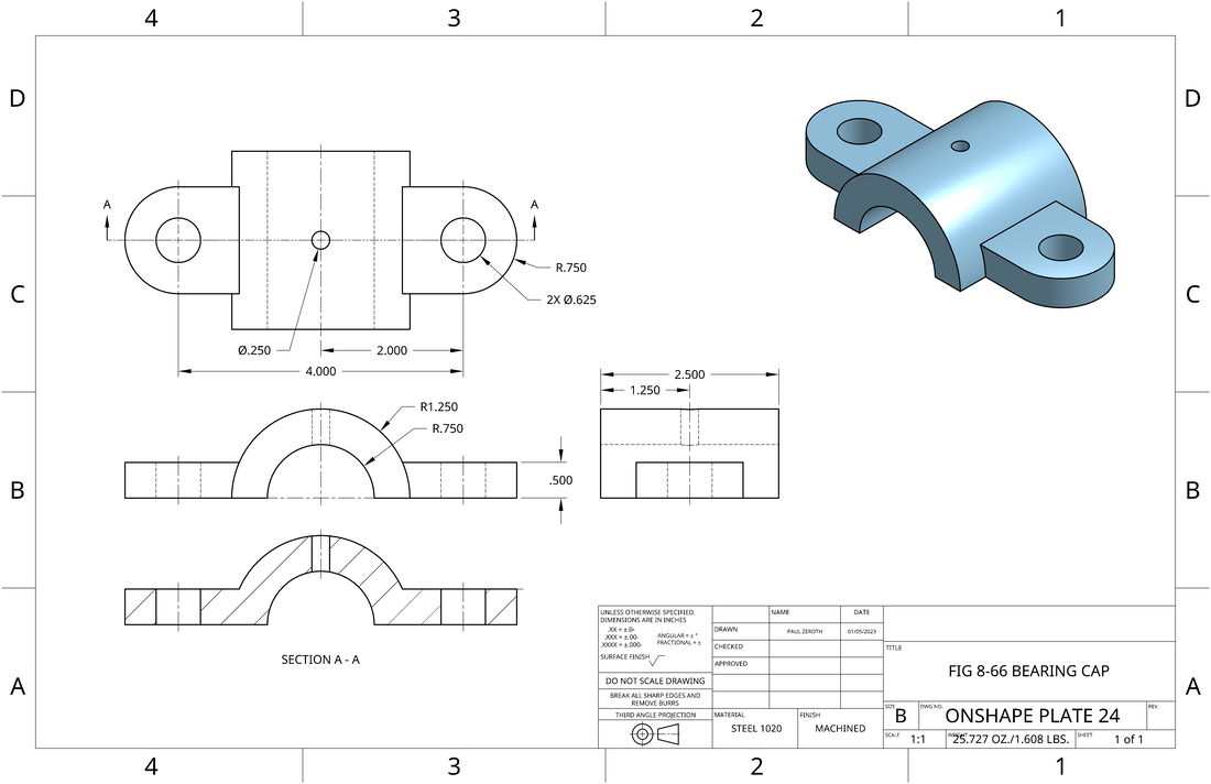
OnShape Plate 18-Fig 8-66-Bearing Cap-(Material-400 Series Stainless Steel) Ortho with dimensions with Shaded Isometric and Full Section
OnShape Plate 19-Fig 11-34-Swivel-(Material-Cast Iron) Ortho with dimensions with Shaded Isometric
OnShape Plate 20-Fig 11-35-Control Base-(Material-Cast Iron) Ortho with dimensions with Shaded Isometric
OnShape Plate 21-Fig 11-38-Double Shifter Yoke-(Material-Cast Iron) Ortho with dimensions with Shaded Isometric-No Fillet on Shaft Support
OnShape Plate 22-Fig 11-39 Double Shifter-(Material-Cast Iron) Ortho with dimensions with Shaded Isometric-ANSI "C" PAPER
OnShape Sections
OnShape Plate 28-Full Section Fig 12-30 #1. Adjustment Block
OnShape Plate 29-Broken Section Section Fig 12-30 #3. Saddle Block with Broken Section on Front view A-A and Right Side view as a Full Section B-B
OnShape Plate 30-Offset Section Fig 12-30 #4. Holder Base
OnShape Auxiliaries
OnShape Plate 31-Auxiliary Fig 13-27. Contact Arm. Show drawing as shown in arrangement of views thumbnail
OnShape Plate 32-Auxiliary Fig 13-21 #2. Holder Pivot. Show both auxiliary views perpendicular to the 45° and 60°
OnShape Plate 33-Auxiliary Fig 13-21 #3. Flanged 45° Elbow. Show both full auxiliary views without hidden lines. Flange plates are offset 45° from each other
OnShape Multi-Part Studio
Multi-Part Part Studios
Complete the exercises contained within the tutorial
-Creating a Master Sketch
-Creating Multiple Parts in a the Parts Studio
OnShape Assembly
Onshape Assemblies
Introduction to Assembly Design
Complete the exercises contained within the tutorial
-Insert a Part
-Mating Parts
-Assembly
OnShape Threads and Fasteners
Follow class demo
OnShape Plate 34. Bolt with external threads-Follow demonstration
OnShape Plate 35. Plate with internal threads-Follow demonstration
Final Working Drawings with Assembly and Parts List
OnShape Plate 36-Fig 16-35. Caster
Extra
Your Choice-Include in portfolio and turn in with self assessment
Mechanical Drawings
Plate 1 - Fig 4-51 Drafting Room Layout-Draw to scale 1/4" = 1'-0"
Plate 2 - Fig 8-43 Adjustor Block-Orthographic (T, F, RS) with Dimensions
Plate 3 - Fig 8-44 Riveting Hammer Head-Orthographic (T, F, RS) with Dimensions
Plate 4 - Fig 8-45 Flipper Dog-Orthographic (T, F, RS) with Dimensions
Plate 5 - Fig 8-46 Guide Base-Orthographic (T, F, RS) with Dimensions
Plate 6 - Working drawings for parts 1-5 of Tool Makers Vise
Plate 7 - Isometric Exploded Assembly for Tool Makers Vise
AutoCAD Drawings-Single View
Plate 8 - Fig 4-59 Gasket-Single View with Dimensions
Plate 9 - Fig 6-34 Handwheel-Convert metric to English Imperial-Single View with Dimensions
Plate 10 - Fig 6-37 Quadrant for Lathe-Convert metric to English Imperial-Single View with Dimensions. Scale 1:2
Plate 11 - Fig 6-39 Locomotive Truck Swing Link-Single View with Dimensions. Scale 1:2
Plate 12 - Fig 6-44 Buick Rear Transmission Gasket-Single View with Dimensions.
AutoCAD Drawings-Orthographic Projection
Plate 13 - Fig 8-47 Holder Base-Orthographic Projection with Dimensions
Plate 14 - Fig 8-49 Jig Block-Orthographic with Projection with Dimensions
Plate 15 - Fig 8-51 Switch Dog-Orthographic Projection with Dimensions
Plate 16 - Fig 8-54 Tool Post Block-Orthographic Projection with Dimensions
AutoCAD Drawings-Sections
Plate 17 - Fig 12-26 Container Cap-Orthographic Projection with Right Side View as a Full Section with Dimensions
Plate 18 - Fig 12-29 #4-Locating Block-Orthographic with Front View as a Full Section with Dimensions
Plate 19 - Fig 12-38 Flanged Tee-Front & Top View only as a Half Section on both views with Dimensions. Scale: 1:2
Plate 20 - Fig 12-28 Flanged Elbow-Front & Right Side only with Broken Out Section on Front View with Dimensions
Onshape
Review Onshape Basics from Onshape's Self Paced Courses-OnShape Fundamentals Section
- Linkage and Lightbulb looking object
Review Onshape Part Design from Onshape's Self Paced Courses-OnShape Fundamentals Section
- Extrude, Revolve, Sweep, Loft, Coffee Cup
Onshape Detailed Drawings from Onshape's Self Paced Courses-OnShape Fundamentals Section
Onshape Multipart Studio from Onshape's Self Paced Courses-OnShape Fundamentals Section
OnShape Working Drawings
OnShape Plate 13-Fig 8-37-Dovetail A-Ortho with dimensions with Shaded Isometric as practice
OnShape Plate 14-Fig 8-38-Dovetail B-Ortho with dimensions with Shaded Isometric as practice
OnShape Plate 15-Fig 8-61-Wedge Base-(Material-Brass) Ortho with dimensions with Shaded Isometric
OnShape Plate 16-Fig 8-62-Base Bracket-(Material-Iron) Ortho with dimensions with Shaded Isometric
OnShape Plate 17-Fig 8-64-Guide-(Material-Steel 1010) Ortho with dimensions with Shaded Isometric
OnShape Plate 18-Fig 8-66-Bearing Cap-(Material-400 Series Stainless Steel) Ortho with dimensions with Shaded Isometric and Full Section
OnShape Plate 19-Fig 11-34-Swivel-(Material-Cast Iron) Ortho with dimensions with Shaded Isometric
OnShape Plate 20-Fig 11-35-Control Base-(Material-Cast Iron) Ortho with dimensions with Shaded Isometric
OnShape Plate 21-Fig 11-38-Double Shifter Yoke-(Material-Cast Iron) Ortho with dimensions with Shaded Isometric-No Fillet on Shaft Support
OnShape Plate 22-Fig 11-39 Double Shifter-(Material-Cast Iron) Ortho with dimensions with Shaded Isometric-ANSI "C" PAPER
OnShape Sections
OnShape Plate 28-Full Section Fig 12-30 #1. Adjustment Block
OnShape Plate 29-Broken Section Section Fig 12-30 #3. Saddle Block with Broken Section on Front view A-A and Right Side view as a Full Section B-B
OnShape Plate 30-Offset Section Fig 12-30 #4. Holder Base
OnShape Auxiliaries
OnShape Plate 31-Auxiliary Fig 13-27. Contact Arm. Show drawing as shown in arrangement of views thumbnail
OnShape Plate 32-Auxiliary Fig 13-21 #2. Holder Pivot. Show both auxiliary views perpendicular to the 45° and 60°
OnShape Plate 33-Auxiliary Fig 13-21 #3. Flanged 45° Elbow. Show both full auxiliary views without hidden lines. Flange plates are offset 45° from each other
OnShape Multi-Part Studio
Multi-Part Part Studios
Complete the exercises contained within the tutorial
-Creating a Master Sketch
-Creating Multiple Parts in a the Parts Studio
OnShape Assembly
Onshape Assemblies
Introduction to Assembly Design
Complete the exercises contained within the tutorial
-Insert a Part
-Mating Parts
-Assembly
OnShape Threads and Fasteners
Follow class demo
OnShape Plate 34. Bolt with external threads-Follow demonstration
OnShape Plate 35. Plate with internal threads-Follow demonstration
Final Working Drawings with Assembly and Parts List
OnShape Plate 36-Fig 16-35. Caster
Extra
Your Choice-Include in portfolio and turn in with self assessment
